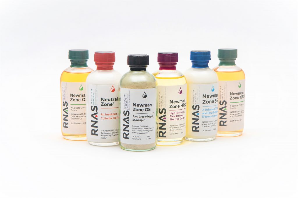
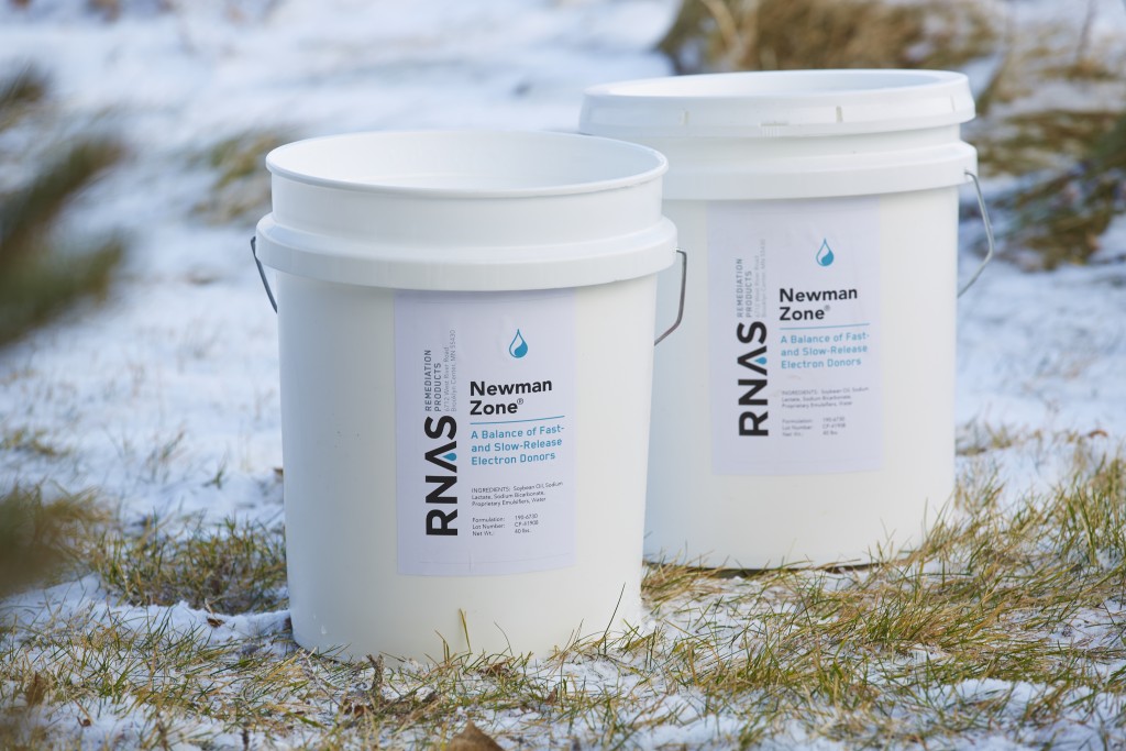
Tips for Injections
| Leaky Hoses Leaky hoses between the injection pumps and wellhead fittings create an inconvenience for the field crew and are not popular with regulators, clients, and casual observers. The leaks have two possible sources; either camlock fittings are improperly connected, or the hose clamps that secure camlock fittings to the vinyl hoses are loose. Solution #1: Make sure that both levers on female camlock fittings are pressed parallel to the axis of the hose. Solution #2: Tighten hose clamps at the source of leaks. No matter how tight we secure the clamps in the shop, the vinyl seems to creep with time and loosen the joints. A large screwdriver or a 5/16" socket can be used to tighten the clamps; the socket will be much kinder to the hand that holds the hose and clamp while tightening. |
|
| Pump Does Not Draw Newman Zone® Failure of the Dosmatic™ pumps to draw Newman Zone® has two possible causes; either the proportional feed of the pump is not turned on or there is a vacuum leak in the intake hose assembly. Solution #1: The Dosmatic™ pump makes loud clicking sounds as it operates. The sounds come from the check valves that sequentially open and close as they draw Newman Zone® and mix it with water. Make sure that the lever at the top of the pump is in the ON position (a red band is visible at the top stem of the pump when the lever is in the OFF position). (Older models do not have this lever; they are always ON). The pump motor is defective if there is no clicking when water passes through the pump and the lever is ON. Solution #2: Find the leak: 1) Make sure the end of the intake hose is at the bottom of the tote or pail. The pumping action of the Dosmatic™ pump will cause the intake hose to work itself out of the tote or pail. You can use one of the straps that hold the tote to its pallet to tie the intake hose to the fill opening at the top of the tote. 2) Tighten all of the hose clamps on the intake hose and Y-hose. 3) Make sure that all of the camlock fittings are properly connected. 4) Make sure the check valve at the bottom of the Dosmatic is hand tight to the pump. 5) The check valve screws together like a union. Make sure the valve itself is hand tight. If you remove the check valve, DON'T LOOSE THE O-RING! YOU WON'T FIND A REPLACEMENT LOCALLY! 6) If none of these steps provides a cure, the problem is probably a worn piston. Call us for a part and check the Dosmatic instructions for the pump model you are using. |
|
| Pump Draws Too Much Newman Zone® It may happen that Newman Zone® is pulled from a tote or pail at a rate significantly greater than the setting on the Dosmatic™ pump. Solution #1: If the discrepancy is small, remember that the markings on the Dosmatic™ are nominal ("in name only"). You may wish to fine-tune the setting by comparing the amount of Newman Zone® used to the pump discharge. You will need either a pail or garbage can marked according to volume or weighed with a waterproof bathroom scale. Solution #2: Flow rates are not accurate. There are three measures of flow in each 10-channel system - two digital meters on the injection skid, 10 mechanical meters on the injection skid, and one digital flow meter on each wellhead unit. The sums will not be identical, but should be close recognizing that the digital meters will not be accurate at very low flows (< 0.5 gpm per well). Solution #3: The check valve at the bottom of the Dosmatic™ pump is failing to close with each piston stroke which results in the siphoning of Newman Zone® from its source. Test this by removing the check valve from the bottom of the pump. The check valve has failed if Newman Zone® continues to flow through it after removal from the Dosmatic™. Consult the Plastomatic documentation for the check valve to clean it or contact us for a replacement. WARNING: Do not overtighten the check valve during reassembly. This is the main cause of distorting the diaphragm and causing a leak. |
|
| Pumping Low Flow Rates with a 10-Channel Injection System Tight soils may limit injection rates to a few gallons per minute, or even significantly less. Yet, it may be desirable to use a 10-channel injection system to minimize time in the field. If the total flow is less than 40-50% of the nominal capacity of a single pump (20 gpm for A20's and 30 gpm for A30's), we recommend that you valve off one Dosmatic™ pump and allow the entire injection volume to pass through the other pump. Either pump alone will feed all ten channels. |
|
| Initial Injection Rates That Are Faster Than Expected Your hydrogeologist told you that 0.5 gpm per well was all that you would get. Yet after setting up, you're pumping 5 gpm into each well. Your hydrogeologist had a reason for his estimate and that reason might come back to bite. In tight materials, high injection rates mean high head at the well. Under such conditions, you may find that the injected fluid is being driven toward the surface near the well rather than being pushed laterally through the aquifer. The resulting cone of impression will eventually saturate the vadose zone and then break through to the surface, creating a "spring-fed" lake or stream of opaque white liquid that will make an unpopular impression with all concerned. Experience gained during injection may indicate that acceptable injection rates will be greater than predicted; just don't get greedy. |
|
| Draining Totes The vacuum necessary for the injection system to extract Newman Zone® will be broken when the level is lowered to the point where the amendment hose inlet is exposed to air. At this point, there will still be 10 gallons or so of Newman Zone® in the tote. As the level of Newman Zone® nears the bottom of the tote, start to pull the polyethylene liner from the cardboard walls and gather it around the amendment hose in a manner that increases the depth of liquid. The liner can be held against the amendment hose either by hand (in situations where extraction from the tote is relatively fast) or by tape, bungee, or zip tie. Make sure that the end of the amendment hose is either flat on the tote bottom or is pointing downward. As the volume of Newman Zone® decreases, continue to "choke up" toward the end of the amendment hose, pulling the liner up the hose, and decreasing the volume of the liner and the length of the hose below the hand. Keep the inlet screen at the lowest point of the liner. At the end, you will be holding the amendment hose just above the intake screen and pointing downward with the liner tight against the screen. Virtually all Newman Zone® can be extracted from a tote in this manner. When the tote is empty, the liner can be tossed in the trash or recycled as polyethylene. It will have a lot of greasy stuff on it, so some plastics recyclers may not want it. The pallets obviously can be reused; they are very good quality, so someone may be willing to take them for reuse or resale. The tote lid and bottom cardboard sheets are single-ply and take up very little volume. Just pull them out and you will have thin 44x44-inch sheets that are easy to stack. The totes use the pallet for the structural strength of the bottom. The tote walls are 8-ply cardboard about 1.5-inches thick. The walls are made as a square tube held in shape by diagonal flaps at the top and bottom. Either cut or fold the flaps in and fold the tote walls into a flat sheet about 3-inches thick and 4x8 feet in size. You can either put them in a cardboard recycling dumpster or strap them into double pallet bales and have someone pick them up for recycling. If someone has kids, the totes make awesome forts! However one or two totes per kid is probably sufficient for this purpose. Not many parents will want 20 of them in their yard. |
|
| Draining Bulk Tanks Newman Zone® will gravity feed directly from bulk Agmark tanks. However, drainage will be slow if the feed hose is long (less than 1 gpm through 200' of 3/4" i.d. hose). The tank can be pressurized with nitrogen to 30 psi which will significantly increase the feed rate. We can supply the fittings needed to plumb the tank to our injection equipment and to pressurize the tank. Getting the last drop of Newman Zone® from a pail or tote is a simple job for one worker. A 5,000 gallon tank is somewhat more difficult to handle. Use a carpenter's level to level the trailer/tank unit from side to side and provide a slight pitch from front to rear. |
|
| Freeze-Proofing Winters are cold at our Minnesota headquarters and Wisconsin warehouse. One consequence is that injection equipment can freeze during shipping or while sitting on a loading dock. The result is expensive. The proportional feed pumps and even galvanized iron fittings and bronze valves have broken as the result of freezing. It is virtually impossible to drain all of the water from the injection systems, even with repetitive tumbling. Hence, we routinely fill our injection systems with propylene glycol to prevent freezing because they are stored remotely and we never know when they will be needed. The propylene glycol that we use is manufactured to winterize potable water supply systems in RV and marine applications. There is no problem in pumping the small amount (~2 gallons for a 10-channel system) into the ground as injection begins; the bacteria will love it. However, regulators and shippers may not be quite so open-minded. To allay any fears, we have provided the manufacturer's MSDS for their product. The 10-channel systems are shipped with 5 gallons of propylene glycol and a 12v pump to winterize them for return shipping (see Freeze-Proofing the System for Winter Shipping). One-channel systems are shipped with 1 gallon of propylene glycol and a hand pump. This step is not necessary from mid-spring through mid-fall. Simply return the jugs with the rest of the equipment. |
|
| Locking Well Caps Locking well caps exist for a good reason, but they will not allow our wellhead compression coupling to slip over the end of the casing. Solution #1 is to remove the locking well cap until injection is complete. Solution #2 is to use 2" casing and have an aquifer that will accept your desired injection rate under a head that is less than the depth to ground water. Then you can simply slip the wellhead unit into the casing and let gravity do the work. If you have a suitable aquifer but smaller casing, you could make up your own funnel with PVC pipe and a PVC reducing coupler. If 1" casing will slip into the well bore, you could use our 1-1/2" x 1" compression couplings and a short piece of 1" PVC pipe. If 1" casing will slip into the well bore, you could use our 1-1/2" x 1" compression couplings and a short piece of 1" PVC pipe. |
![]() |
| Temporary Wells and Bentonite Grout Injection through temporary casing or push probes can cause problems if aquifer permeability is low. The lack of a seal between casing and native materials will either severely restrict injection rates or the injection fluids will migrate up the annulus and you will have a white puddle around each well. A solution is to use bentonite grout that will allow the casings to be pulled after injection. However, pouring a slurry of bentonite granules down the annulus will not solve this problem. The fluid grout will still allow injection fluids under pressure to move up the annulus Solution #1 is to not make a bentonite slurry that is then poured into the annulus around the well because most of the expansion of the bentonite will occur in your mixing bucket. Instead, place dry bentonite ( 3/4" chips work well) in the annulus and then hydrate with water. That way, the bentonite expansion occurs in the annulus and creates a significantly tighter seal. Injection pressures might still need to be modest (3-7 psi.). Solution #2 is to use a cement grout. Then the strength of the seal will not be the limiting factor to injection rates and pressures. |
|
| Well Manholes Our wellhead units attach to 1" or 2" well casings with our own PVC reducing compression fittings (1"x1-1/2" or 1-1/2"x2"). A well manhole protects the well casing in areas of heavy traffic. But tigntening the compression fitting inside a small manhole can be difficult to impossible. Either there is not enough room in the manhole to tighten the coupling with a strap wrench (we like the Westward Boa Constrictor - you'll need two; carried by Grainger - 5PV88) or your driller did not leave enough of a stub to attach the compression fitting (at least 2" is needed). Solution #1 is don't use a small manhole. Solution #2 is don't cut the casing below grade prior to injection. Solution #3 is to glue a PVC Socket x Pipe Thread coupling to the casing and make up a short piece of PVC pipe with the corresponding Socket x Pipe Thread coupling to extend the well casing during injection. Then our wellhead compression coupling can then be attached to the extension. The extension can be replaced with a threaded cap or plug (depending on which sex coupling you glued to the casing) when injection is complete. Solution #4 is to use a Fernco flexible pipe connector and an L-shaped screwdriver to tighten the hose clamps. Be aware that we rate our compression couplings at 20 psi (they will start to slide off PVC casing at 30 psi), whereas Fernco rates their couplings at 4.3 psi maximum test pressure. Note that the throttling valve and pressure gauge on each wellhead assembly will allow you to inject at the maximum rate without exceeding these pressure limits. Solution #5 is to use 2" casing and have an aquifer that will accept your desired injection rate under a head that is less than the depth to ground water. Then you can simply slip the wellhead unit into the casing and let gravity do the work. If you have a suitable aquifer but smaller casing, you could make up your own funnel with PVC pipe and a PVC reducing coupler. If 1" casing will slip into the well bore, you could use our 1-1/2" x 1" compression couplings and a short piece of 1" PVC pipe. |
![]() ![]() |
| Well Screens and Cottage Cheese In many cases, an injection well will later be used for a second injection or for monitoring. Any electron donor, regardless of manufacturer, that remains in a well bore after injection will attract bacteria if other conditions conducive to growth are present. The result may be a well bore that is filled with a bacterial mess that looks like cottage cheese. Solution #1 is to inject 100 gallons or so of clean water into each well after the injection has been completed. Simply put the amendment hose in a bucket of water and continue to operate the injection system. This will clean both the system and the well bore(s). The purpose is NOT to chase the Newman Zone® farther into the aquifer, but to simply clear the well bore, screen, and pack so that the well will not biofoul. |
|


